
Playing ping-pong with single electrons
Quantum dots (QDs) provide a useful system for manipulating and storing quantum information. Methods for moving quantum information (spin) between processor and storage, or to a region of holes for conversion to photon qubits, will be required. Tunnelling of electrons over long distances between QDs is not viable. We have achieved controlled long-range transfer of single electrons between QDs through a depleted 1D channel using pulses of surface acoustic waves (SAWs).
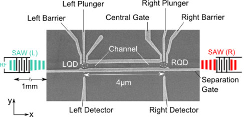
In our device, two QDs are connected by a 4 μm channel with QD occupancy monitored by 1D charge detectors. Electrons may be trapped and raised above the Fermi energy by stepping gate voltages. Having set the first QD to be ‘full’ and the other QD ‘empty’, a short SAW pulse is sent to transfer the electron to the opposite QD. This bi-directional process may be repeated over 100 times with the same electron. SAW power and pulse-width dependences suggest that transfer is achieved during the first few SAW cycles, allowing sub-20 ns pulses to be used.
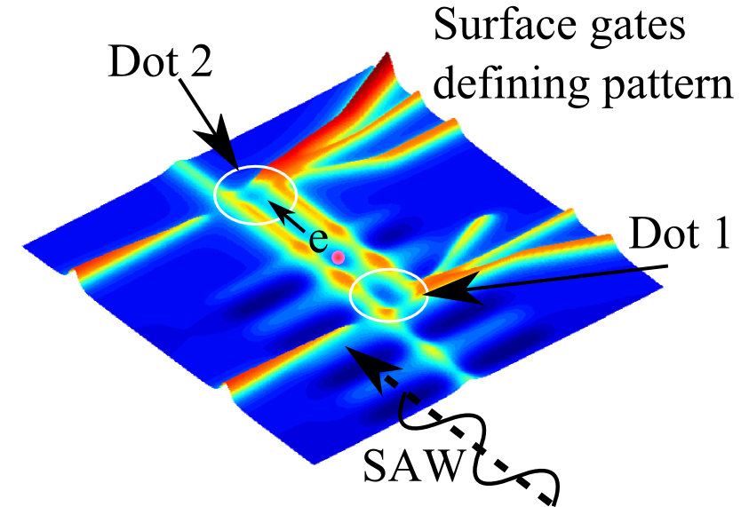
A SAW pulse can be used to take an individual electron from one isolated quantum dot to another (from a dot at bottom right in the above figure, to one at top left). The quantum dots and the channel joining them are isolated from reservoirs by large barrier potentials. The energy levels in the dots and channel are above the Fermi energy, so other electrons have too little energy to enter the system.
The following animation shows how the transfer process occurs.
Please allow social and marketing cookies to show embedded content.
The device is shown in Figure 3. The left and right QDs are labelled LQD and RQD respectively.
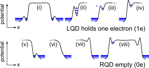
The initialisation method is shown in Figure 4. In (i) to (iv), LQD is filled with one electron by changing the barrier and plunger gates. In (v) to (viii), RQD is initialised using a different order of gate voltage changes, to ensure it contains no electrons.
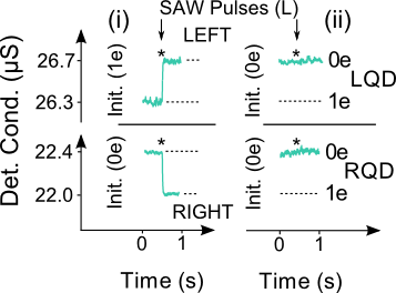
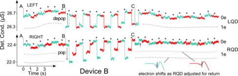
The detector constrictions next to each QD change their conductance depending on how many electrons are in the dot. When a SAW pulse arrives from the left, LQD loses its electron, so there is a sudden step up in the detector conductance (upper panel, Fig. 5(i)). At the same time an electron appears in RQD (shown by the sudden step down in its detector conductance (lower panel, Fig. 5(i). When the dots are both initialised to be empty, a SAW pulse has no such effect (Fig. 5(ii)), showing that it is the same electron that has moved from one dot to the other.
The electron can then be transferred back to LQD by sending in another SAW pulse, from the opposite direction. The steps in the detector conductances are now in the opposite directions. Fig. 6 shows a series of pulses, shown alternately as red and green. Initially the dots are both empty and no steps are seen. Then LQD is initialised with one electron, and SAW pulses are sent alternately from left and right, transporting the electron from left to right, or back again, 10 times, in the region between labels B and C. At point C, the electron is allowed to leave the system, and subsequent pulses show no sign of any other electrons. Up to 60 faultless transfers have been observed sequentially. After that, the usual ways in which the process fails are that the electron gets stuck temporarily in the channel (but reappears), or that an extra electron appears, probably dragged up from the reservoirs by the SAW - this should be easy to avoid in future devices by modifying the barriers around the dots.
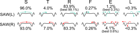
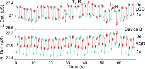
In order to assess our current single-electron transfer reliability, we have measured how likely each transfer or failure is. Figure 7 shows diagrams of the various events that occur, together with their probabilities in our current devices. Figure 8 shows a long sequence of transfers, labelling the non-ideal events that sometimes occur.
Other aspects of our work on using SAWs for quantum-computing related applications are described here.